 MENU
MENU


NOTE!
Click on MENU to Browse between Subjects...17CS52 - COMPUTER NETWORKS
Answer Script for Module 2
Solved Previous Year Question Paper
CBCS SCHEME
COMPUTER NETWORKS
[As per Choice Based Credit System (CBCS) scheme]
(Effective from the academic year 2019 -2020)
SEMESTER - V
Subject Code 17CS52
IA Marks 40
Number of Lecture Hours/Week 04
Exam Marks 60
These Questions are being framed for helping the students in the "FINAL Exams" Only
(Remember for Internals the Question Paper is set by your respective teachers).
Questions may be repeated, just to show students how VTU can frame Questions.
- ADMIN
1.0 TCP Connection Management
1.1 Connection Setup & Data Transfer
To setup the connection, three segments are sent between the two hosts. Therefore, this process is referred to as a three-way handshake.
Suppose a client-process wants to initiate a connection with a server-process.
The Below Figure Represents the TCP Three-Way Handshake.
Step 1: Client sends a connection-request segment to the Server
a. The client first sends a connection-request segment to the server.
b. The connection-request segment contains:
i. SYN bit is set to 1.
ii. Initial sequence-number (client_isn).
c. The SYN segment is encapsulated within an IP datagram and sent to the server.
Step 2: Server sends a connection-granted segment to the Client
a. Then, the server
i. extracts the SYN segment from the datagram
ii. allocates the buffers and variables to the connection and
iii. sends a connection-granted segment to the client.
b. The connection-granted segment contains:
i. SYN bit is set to 1.
ii. Acknowledgment field is set to client_isn+1.
iii. Initial sequence-number (server_isn).
Step 3: Client sends an ACK segment to the Server
a. Finally, the client
i. allocates buffers and variables to the connection and
ii. sends an ACK segment to the server
b. The ACK segment acknowledges the server.
c. SYN bit is set to zero, since the connection is established.
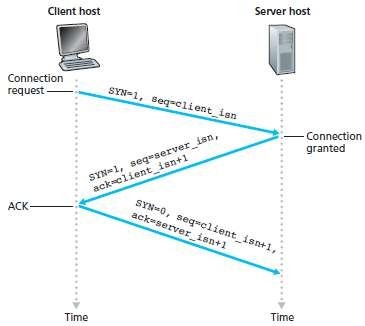
Fig 1.1: TCP three-way handshake: segment exchange
1.2 Connection Release
a. Either of the two processes in a connection can end the connection.
b. When a connection ends, the "resources" in the hosts are de-allocated.
c. Suppose the client decides to close the connection.
d. Figure 1.2 illustrates the steps involved:
i. The client-process issues a close command.
v Then, the client sends a shutdown-segment to the server.
v This segment has a FIN bit set to 1.
ii. The server responds with an acknowledgment to the client.
iii. The server then sends its own shutdown-segment.
v This segment has a FIN bit set to 1.
iv. Finally, the client acknowledges the server's shutdown-segment.
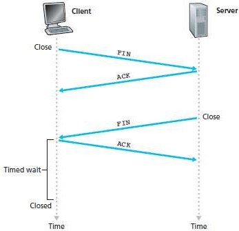
Fig 1.2: Closing a TCP connection
2.1 Go-Back N Protocol (GBN)
a. The sender is allowed to transmit multiple packets without waiting for an acknowledgment.
b. But, the sender is constrained to have at most N unacknowledged packets in the pipeline.
a. Where N = window-size which refers maximum no. of unacknowledged packets in the pipeline
c. GBN protocol is called a sliding-window protocol.
d. Figure 2.1 shows the sender's view of the range of sequence-numbers.
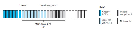
Fig: 2.1 Sender's view of sequence-numbers in Go-Back-N
• Figure 2.2 and 2.3 give a FSM description of the sender and receivers of a GBN protocol.
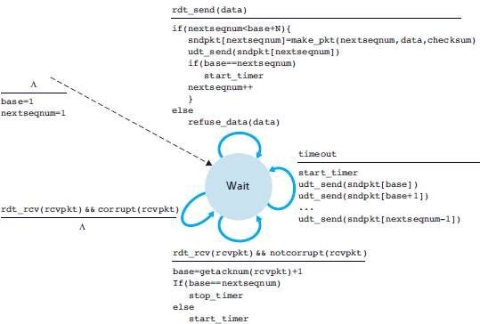
Fig 2.2: Extended FSM description of GBN sender
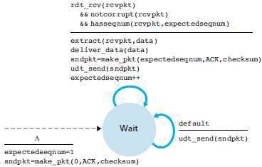
Fig 2.3: Extended FSM description of GBN receiver
2.2 GBN Sender
The sender must respond to 3 types of events:
1) Invocation from above.
When rdt_send() is called from above, the sender first checks to see if the window is full
i.e. whether there are N outstanding, unacknowledged packets.
i. If the window is not full, the sender creates and sends a packet.
ii. If the window is full, the sender simply returns the data back to the upper layer. This is an implicit indication that the window is full.
2) Receipt of an ACK.
a. An acknowledgment for a packet with sequence-number n will be taken to be a cumulative acknowledgment.
b. All packets with a sequence-number up to n have been correctly received at the receiver.
3) A Timeout Event.
A timer will be used to recover from lost data or acknowledgment packets.
i. If a timeout occurs, the sender resends all packets that have been previously sent but that have not yet been acknowledged.
ii. If an ACK is received but there are still additional transmitted but not yet acknowledged packets, the timer is restarted.
iii. If there are no outstanding unacknowledged packets, the timer is stopped.
2.3 GBN Receiver
a. If a packet with sequence-number n is received correctly and is in order, the receiver
i. sends an ACK for packet n and
ii. delivers the packet to the upper layer.
b. In all other cases, the receiver
i. discards the packet and
ii. resends an ACK for the most recently received in-order packet.
2.4 Operation of the GBN Protocol
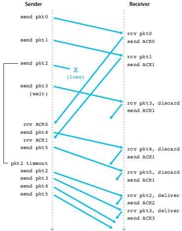
Fig 2.4: Go-Back-N in operation
a. Figure 2.4 shows the operation of the GBN protocol for the case of a window-size of four packets.
b. The sender sends packets 0 through 3.
c. The sender then must wait for one or more of these packets to be acknowledged before proceeding.
d. As each successive ACK (for ex, ACK0 and ACK1) is received, the window slides forward and the sender transmits one new packet (pkt4 and pkt5, respectively).
e. On the receiver, packet 2 is lost and thus packets 3, 4, and 5 are found to be out of order and are discarded.
a. Each TCP connection has exactly 2 end-points.
b. Thus, 2 arriving TCP segments with different source-port-nos will be directed to 2 different sockets, even if they have the same destination-port-no.
c. A TCP socket is identified by a four-tuple:
i. Source IP address
ii. Source-port-no
iii. Destination IP address &
iv. Destination-port-no.
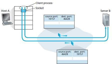
Fig 3.1 : The inversion of source and destination-port-nos
a. The server-host may support many simultaneous connection-sockets.
b. Each socket will be
i. attached to a process.
ii. identified by its own four tuple.
c. When a segment arrives at the host, all 4 fields are used to direct the segment to the appropriate socket. (i.e. Demultiplexing).
The situation is illustrated in Figure 3.1, in which Host C initiates two HTTP sessions to server B, and Host A initiates one HTTP session to B. Hosts A and C and server B each have their own unique IP address-A, C, and B, respectively. Host C assigns two different source port numbers (26145 and 7532) to its two HTTP connections. Because Host A is choosing source port numbers independently of C, it might also assign a source port of 26145 to its HTTP connection. But this is not a problem-server B will still be able to correctly demultiplex the two connections having the same source port number, since the two connections have different source IP addresses.
4.1 Definition
A state occurring in network layer when the message traffic is so heavy that it slows down network response time.
Effects
of Congestion
- As delay increases, performance decreases.
· If delay increases, retransmission occurs, making situation worse.
4.2 Cause of congestion
The Causes and the Costs of Congestion Scenario are as follows:
Scenario 1: Two Senders, a Router with Infinite Buffers
a. Two hosts (A & B) have a connection that shares a single-hop b/w source & destination.
b. This is illustrated in Figure 4.1.
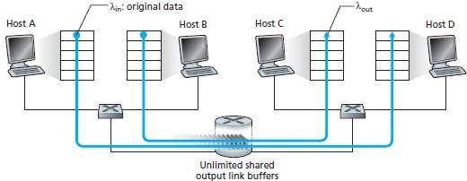
Fig 4.1 Congestion scenario 1: Two connections sharing a single hop with infinite buffers
Let
Sending-rate of Host-A = λin bytes/sec
Outgoing Link's capacity = R
a. Packets from Hosts A and B pass through a router and over a shared outgoing link.
b. The router has buffers.
c. The buffers stores incoming packets when packet-arrival rate exceeds the outgoing link's capacity.
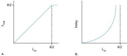
Fig 4.2: Congestion scenario 1: Throughput and delay as a function of host sending-rate
Left Hand Graph
a. The left graph plots the per-connection throughput as a function of the connection-sending-rate.
b. For a sending-rate b/w 0 and R/2, the throughput at the receiver equals the sender's sending-rate. However, for a sending-rate above R/2, the throughput at the receiver is only R/2. (Figure 4.2a)
c. Conclusion: The link cannot deliver packets to a receiver at a steady-state rate that exceeds R/2.
Right Hand Graph
a. The right graph plots the average delay as a function of the connection-sending-rate (Figure 4.2b).
b. As the sending-rate approaches R/2, the average delay becomes larger and larger. However, for a sending-rate above R/2, the average delay becomes infinite.
c. Conclusion: Large queuing delays are experienced as the packet arrival rate nears the link capacity.
Scenario 2: Two Senders and a Router with Finite Buffers
• Here, we have 2 assumptions (Figure 2.37):
1)
The amount of router buffering is finite.
Ø Packets will be dropped when arriving to an already full buffer.
2)
Each connection is reliable.
Ø If a packet is dropped at the router, the sender will eventually retransmit it.
• Let
Application's sending-rate of Host-A = λin bytes/sec
Transport-layer's sending-rate of Host-A = λin' bytes/sec (also called offered-load to network)
Outgoing Link's capacity = R
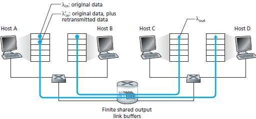
Fig 4.3: Scenario 2: Two hosts (with retransmissions) and a router with finite buffers
Case 1 (Figure 4.4(a)):
Ø Host-A sends a packet only when a buffer is free.
Ø In this case,
i. no loss occurs
ii. λin will be equal to λin', and
iii. throughput of the connection will be equal to λin.
Ø The sender retransmits only when a packet is lost.
Ø Consider the offered-load λin= R/2.
Ø The rate at which data are delivered to the receiver application is R/3.
Ø The sender must perform retransmissions to compensate for lost packets due to buffer overflow.
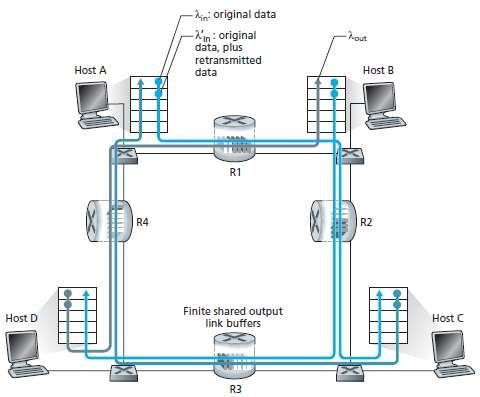
Fig 4.4: Scenario 2 performance with finite buffers
Case 2 (Figure 4.4(c)):
a. The sender may time out & retransmit a packet that has been delayed in the queue but not yet lost.
b. Both the original data packet and the retransmission may reach the receiver.
c. The receiver needs one copy of this packet and will discard the retransmission.
d. The work done by the router in forwarding the retransmitted copy of the original packet was wasted.
Scenario 3: Four Senders, Routers with Finite Buffers, and Multi-hop Paths
• Four hosts transmit packets, each over overlapping two-hop paths.
• This is illustrated in Figure 4.5.
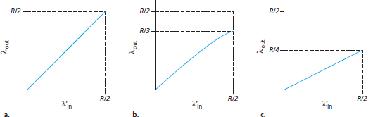
Fig 4.5: Four senders, routers with finite buffers, and multihop paths
Ø Consider the connection from Host-A to Host C, passing through routers R1 and R2.
Ø The A-C connection
o shares router R1 with the D-B connection and
o shares router R2 with the B-D connection.
Ø Case-1:
For extremely small values of λin,
o buffer overflows are rare (as in congestion scenarios 1 and 2) and
o the throughput approximately equals the offered-load.
Ø Case-2:
For slightly larger values of λin, the
corresponding throughput is also larger. This is because
o more original data is transmitted into the network
o data is delivered to the destination and
o → overflows are still rare.
Ø Case-3:
For extremely larger values of λin.
o Consider router R2.
o The A-C traffic arriving to router R2 can have an arrival rate of at most R regardless of the value of λin.
§ where R = the capacity of the link from R1 to R2,.
o If λin' is extremely large for all connections, then the arrival rate of B-D traffic at R2 can be much larger than that of the A-C traffic.
o The A-C and B-D traffic must compete at router R2 for the limited amount of buffer-space.
o Thus, the amount of A-C traffic that successfully gets through R2 becomes smaller and smaller as the offered-load from B-D gets larger and larger.
o In the limit, as the offered-load approaches infinity, an empty buffer at R2 is immediately filled by a B-D packet, and the throughput of the A-C connection at R2 goes to zero.
o When a packet is dropped along a path, the transmission capacity ends up having been wasted.
a. The segment consists of header-fields and a data-field.
b. The data-field contains a chunk-of-data.
c. When TCP sends a large file, it breaks the file into chunks of size MSS.
d. Figure 5.1 shows the structure of the TCP segment.
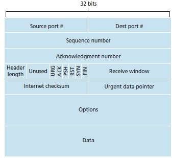
Fig 5.1: TCP segment structure
The fields of TCP segment are as follows:
1) Source and Destination Port Numbers
i. These fields are used for multiplexing/demultiplexing data from/to upper-layer applications.
2) Sequence Number & Acknowledgment Number
i. These fields are used by sender & receiver in implementing a reliable data-transfer-service.
3) Header Length
i. This field specifies the length of the TCP header.
4) Flag
i. This field contains 6 bits.
i) ACK
¤ This bit indicates that value of acknowledgment field is valid.
ii) RST, SYN & FIN
¤ These bits are used for connection setup and teardown.
iii) PSH
¤ This bit indicates the sender has invoked the push operation.
iv) URG
¤ This bit indicates the segment contains urgent-data.
5) Receive Window
i. This field defines receiver's window size
ii. This field is used for flow control.
6) Checksum
i. This field is used for error-detection.
7) Urgent Data Pointer
i. This field indicates the location of the last byte of the urgent data.
8) Options
i. This field is used when a sender & receiver negotiate the MSS for use in high-speed networks.
Below Page NAVIGATION Links are Provided...
All the Questions on Question Bank Is SOLVED