 MENU
MENU


NOTE!
Click on MENU to Browse between Subjects...17CS63 - System Software and Compiler Design
6TH SEMESTER ISE & CSE
Answer Script for Module 1
Solved Previous Year Question Paper
CBCS SCHEME
System Software and Compiler Design
[As per Choice Based Credit System (CBCS) scheme]
(Effective from the academic year 2017 - 2018)
SEMESTER - VI
Subject Code 17CS63
IA Marks 40
Number of Lecture Hours/Week 3
Exam Marks 60
These Questions are being framed for helping the students in the "FINAL Exams" Only
(Remember for Internals the Question Paper is set by your respective teachers).
Questions may be repeated, just to show students how VTU can frame Questions.
- ADMIN
17CS63 - System Software and Compiler Design
6TH SEMESTER ISE & CSE
Answer Script for Module 1
1.1 General Instruction Format:
All machine instructions on the standard version of SIC have the following 24-bit format:

The flag bit x is used to indicate indexed-addressing mode.
1.2 SIC/XE Instruction Format: "SIC == Simplified Instructional
Computer"
The larger memory available on SIC/XE means that an address will (in general) no longer fit into a 15-bit field; thus the instruction format used on the standard version of SIC is no longer suitable.
There are two possible options - either use some form of relative addressing, or extend the address field to 20 bits. Both of these options are included in SIC/XE (Format 3 & 4).
In addition, SIC/XE provides some instructions that do not reference memory at all. Formats 1 and 2 in the following description are used for such instructions.
The new set of instruction formats is as follows:
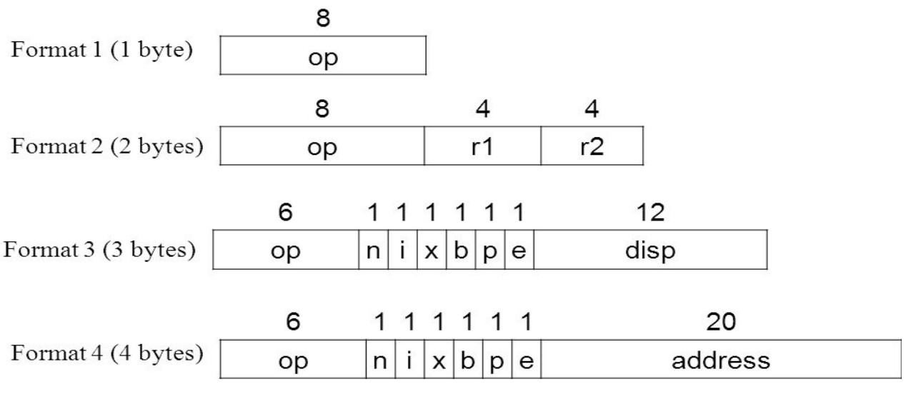
Format-1:
8-bits - only opcode
Format-2:
16 bits - Register to Register operation
Format-3:
24 bits - (e=0) Relative Addressing
Format-4:
32 bits - (e=1) Extended Address
In-Detail:
Format 1 (1 byte):
contains only operation code (straight from table).
Format 2 (2 bytes):
first eight bits for operation code, next four for register 1 and following
four for register 2. The numbers for the registers go according to the
numbers indicated at the registers section (i.e, register T is replaced by
hex 5, F is replaced by hex 6).
Format 3 (3 bytes):
First 6 bits contain operation code, next 6 bits contain flags, last 12
bits contain displacement for the address of the operand. Operation code
uses only 6 bits, thus the second hex digit will be affected by the values
of the first two flags (n and i). The flags, in order, are: n, i, x, b, p,
and e. Its functionality is explained in the next section. The last flag e
indicates the instruction format (0 for 3 and 1 for 4).
Format 4 (4 bytes):
same as format 3 with an extra 2 hex digits (8 bits) for addresses that
require more than 12 bits to be represented.
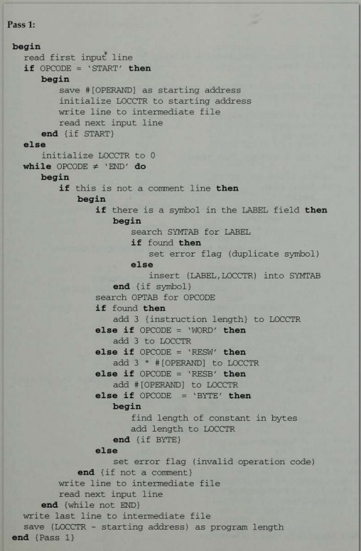
The assembler goes through two passes translate the source program to object code.
Pass 1 - Definition pass
i. Assign addresses to all statement in the program
ii. Store values of all the labels in symbol table
iii. Do processing of declarative statements by assigning the memory
iv. Perform processing of assembler directives
Pass 2 - Translation pass
i. Assemble the instructions by converting mnemonics to op-code and operands to address
ii. Generate data values for constants
iii. Perform processing of assembler directives which is not done in pass 1
iv. Write the object code in appropriate file format
5.1 The Various Machine Independent assembler are as follows:
i. Literals
ii. Symbol-defining statements
iii. Expressions
iv. Program blocks
v. Control sections and program linking
5.2 Control Sections:
A control section
is a part of the program that maintains
its identity after assembly; each such control section can be loaded and
relocated independently of the others.
Different control sections
are most often used for
subroutines or other logical subdivisions of a program. The programmer can
assemble, load, and manipulate each of these control sections separately.
5.3
The Simple SIC Assembler
The assembler performs following functions to translate the source program to object code
:
i. To convert mnemonics to op-code
ii. To convert symbolic operands to address
iii. To convert data constants to machine equivalent representation
iv. To resolve declarative statements and assembler directives
v. Write object code and assembly listing
Below Page NAVIGATION Links are Provided...
All the Questions on Question Bank Is SOLVED