 MENU
MENU


NOTE!
Click on MENU to Browse between Subjects...17CS62 - COMPUTER GRAPHICS AND VISUALIZATION
6TH SEMESTER CSE
Answer Script for Module 1
Solved Previous Year Question Paper
CBCS SCHEME
COMPUTER GRAPHICS AND VISUALIZATION
[As per Choice Based Credit System (CBCS) scheme]
(Effective from the academic year 2017 - 2018)
SEMESTER - VI
Subject Code 17CS62
IA Marks 40
Number of Lecture Hours/Week 3
Exam Marks 60
These Questions are being framed for helping the students in the "FINAL Exams" Only
(Remember for Internals the Question Paper is set by your respective teachers).
Questions may be repeated, just to show students how VTU can frame Questions.
- ADMIN
17CS62 - COMPUTER GRAPHICS AND VISUALIZATION
6TH SEMESTER CSE
Answer Script for Module 1
11.1 Computer Graphics:
Computer graphics
is the discipline of generating images with the aid ofcomputers
. Today, computer graphics
is a core technology in digital
photography, film, video games, cell phone and computer
displays, and many specialized
applications. ... It is also used for processing image data received from
the physical world.
11.2 Application:
Refer 1st
Question & Answer or Click Here
Refer 4th
Question & Answer or Click Here

14.1 CRT == Cathode Ray Tube
Figure 14.1 illustrates the basic operation of a CRT.
A beam of electrons
(cathode rays), emitted by anelectron gun
, passes through focusing and deflection systems
that direct the beam
toward specified positions on the phosphor-coated screen
.
The phosphor
then emits
a small spot of
light at each position contacted by the electron beam. Because the light
emitted by the phosphor fades very rapidly
, some method is
needed for maintaining the screen picture.
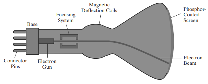
Fig 14.1 Basic design of a magnetic-deflection CRT
.
One way to do this is to store
thepicture information
as a charge distribution
within the CRT. This charge
distribution can then be used to keep the phosphors activated
. However, the most common method now
employed for maintaining phosphor glow is to redraw the picture repeatedly
by quickly directing the
electron beam back over the same screen points. This type of display is
called a refresh CRT
, and the frequency at which a picture
is redrawn on the screen is referred to as the refresh rate.
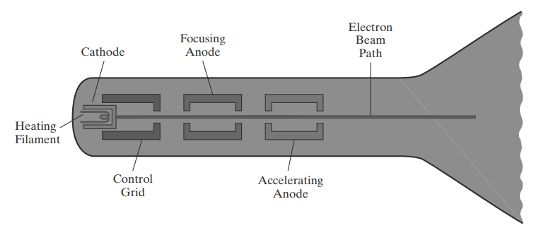
Fig 14.2 Operation of an electron gun with an accelerating anode.
Operation of an electron gun with an accelerating anode:
I. The primary components of an electron gun in a CRT are the heated metal cathode and a control grid.
II. The heat is supplied to the cathode by directing a current through a coil of wire, called the filament, inside the cylindrical cathode structure.
III. This causes electrons to be "boiled off" the hot cathode surface.
IV. Inside the CRT envelope, the free, negatively charged electrons are then accelerated toward the phosphor coating by a high positive voltage.
V. Intensity of the electron beam is controlled by the voltage at the control grid.
VI. Since the amount of light emitted by the phosphor coating depends on the number of electrons striking the screen, the brightness of a display point is controlled by varying the voltage on the control grid.
VII. The focusing system in a CRT forces the electron beam to converge to a small cross section as it strikes the phosphor and it is accomplished with either electric or magnetic fields.
VIII. With electrostatic focusing, the electron beam is passed through a positively charged metal cylinder so that electrons along the center line of the cylinder are in equilibrium position.
IX. Deflection of the electron beam can be controlled with either electric or magnetic fields.
X. Cathode-ray tubes are commonly constructed with two pairs of magnetic-deflection coils.
XI. One pair is mounted on the top and bottom of the CRT neck, and the other pair is mounted on opposite sides of the neck.
XII. The magnetic field produced by each pair of coils results in a traverse deflection force that is perpendicular to both the direction of the magnetic field and the direction of travel of the electron beam.
Below Page NAVIGATION Links are Provided...
All the Questions on Question Bank Is SOLVED